Putting order in the impossible
Zenon Kulpa
Institute of Biocybernetics and Biomedical Engineering. 00-818 Warsaw Poland
[Published in: Perception, 1987, vol. 16, pp. 201-214]
Abstract. The class of visual illusions called 'impossible figures' (illusory spatial interpretations of pictures) is analyzed in order to introduce an ordering into the great variety of such figures. Such an ordering facilitates reference, unifies terminology, and establishes a conceptual framework for further investigations of the subject, making easier the choice and systematic generation of various types of figures (for example, in systematic psychological experiments). First, the notion of 'impossible figure' is defined and certain other related classes of figures (so-called 'likely' and 'unlikely' figures) are distinguished. Second, the fundamental 'impossibility sources' are identified as elementary 'building blocks' of all impossible figures. Finally, two broad classes of impossible figures, multibars or ('impossible polygons') and striped figures, are briefly described.
1 Introduction
Since the publication of the short paper by Penrose and Penrose (1958), so-called 'impossible figures' have increasingly attracted the attention of psychologists, computer scientists, and mathematicians. Psychologists study them as a new type of visual illusion (Penrose and Penrose 1958; Gregory 1970; Young and Deręgowski 1981) providing information about mechanisms of visual perception, in particular the spatial interpretation of pictures (for example, Gregory 1970; Huffman 1971; Cowan and Pringle 1978; Young and Deręgowski 1981; Kulpa 1983; Térouanne 1983; Thro 1983). For similar reasons they draw the attention of computer scientists who work in the field of computer vision and try to create computer models of human perceptive abilities (Huffman 1971; Sugihara 1982a, 1982b; Kulpa 1983). Finally, for mathematicians they represent new types of abstract structures to be formally studied (Huffman 1971; Cowan 1977; Térouanne 1980, 1983). It should also be mentioned that these effects are of increasing interest to the theory and practice of visual arts and graphic design (Ernst 1976, 1985, 1986; Yturralde 1978; Reutersvärd and Kulpa 1984), and that they are also discussed in the contexts of logic and the philosophy of language (Cresswell 1983).
The presentation of just a few examples of the most well-known impossible figures (figure 1) is sufficient to demonstrate the considerable diversity of types that exists. Many more examples could be given, and it is therefore important to find (or impose upon) these figures some ordering principles and classification schemes.

Figure 1. Four examples of impossible figures: (a) Penrose's
tribar; (b)
devil's fork; (c) Thiéry's figure; (d) impossible ring
In this paper I propose and briefly discuss several basic ordering schemes. The presentation starts, in section 2, with the definition of an impossible figure (Kulpa 1983) and a general classification that relates impossible figures to possible figures, and also to special classes of figures called 'likely' and 'unlikely' (Huffman 1971; Kulpa 1983). The problem of various degrees of impossibility is also introduced. In section 3 the fundamental 'impossibility sources' are identified (Cowan and Pringle 1978; Kulpa 1983; Thro 1983) as elementary 'building blocks' of all impossible figures. Finally, in sections 4 and 5, two broad classes of impossible figures, namely multibars (Cowan 1977; Draper 1978; Térouanne 1980; Kulpa 1981) and striped figures (Robinson and Wilson 1973), are briefly described.
The classification schemes described in this paper are based partially on my own investigations (Kulpa 1981, 1983), and partially on the work of others, especially Huffman (1971) and Cowan (1977). Certain other classification schemes, unrelated, in principle, to those I discuss below, have also been proposed. Guiraud and Lison (1976) tried to systematize, from the graphic designer's point of view, the multitude of ambiguous figures based on the principle behind Thiéry's figure (Thiéry 1895; see figure 1c). On the other hand, Sugihara (1982a, 1982b) suggested the general classification of so-called "labelable figures" (which include many possible and impossible figures) according to features significant for certain types of computer algorithms of automatic scene analysis.
2 Impossible, likely, and unlikely figures
Before attempting to classify impossible figures it is important, of course, to define them as precisely as possible.
2.1 What are impossible figures?
The following definition seems to summarize well the intuitive notion of an impossible figure:
An impossible figure is a (flat) drawing that gives an impression of a three-dimensional object such that the object suggested by our spatial interpretation of the drawing cannot exist, that is, an attempt to construct it leads to (geometrical) contradictions clearly visible to the observer.
The three phrases set bold in the definition constitute the key to a proper understanding of the notion of an impossible figure, and should, therefore, be analyzed in more detail.
First, the drawing, to be at all amenable to a judgement of impossibility, should give the impression of a spatial object, that is, it should trigger our spatial interpretation mechanisms. Otherwise, calling it either 'possible' or 'impossible' does not make any sense – no more than asking whether a drawing of a square is possible or impossible. Moreover, the use of the word 'impression' here indicates that the notion of an impossible figure is of a psychological rather than a mathematical nature. It makes us suspect whether a purely formal (for example, geometrical) analysis of this phenomenon is able to provide the means for its full understanding (Kulpa 1983).
Second, when confronted with a drawing that creates an impression of spatiality, our visual system tries to find its spatial shape, orientation, and structure, starting from the analysis of different fragments and depth cues. It then combines and coordinates these partial interpretations in order to arrive at some overall hypothesis about the spatial structure of the whole depicted object (or objects). Usually, despite the fact that any flat drawing can have an infinite number of different spatial interpretations (that is, it might represent an infinite number of spatially different objects), our interpretation mechanisms select only one interpretation, the most 'natural' to us. It is this single 'natural' interpretation of the drawing which is next tested for its possibility, and not the original drawing itself! The impossible interpretation is the one that appears to be contradictory - various partial local interpretations do not fit into a consistent whole. Generally:
The property 'to be an impossible figure' is not the property of the drawing alone, but the property of the spatial interpretation chosen by a human observer.
We call those figures impossible whose most natural (to us here and now) interpretation happens to be impossible. However, this does not mean that some other interpretation of the same figure, perhaps quite possible, does not exist, Thus, finding a method of precise description of spatial interpretations of figures appears to be one of the main issues of further work on impossible figures and spatial interpretation mechanisms. When we are able to describe (for example, formally) various interpretations, we can compare them, relate the figure and its different interpretations (and, possibly, understand the mechanisms responsible for creating various interpretations), check their consistency or discover different types of inconsistency, and so on. It seems that a significant step in this direction has been made by Térouanne (1983).
Thiéry's figure (Thiéry 1895; Gregory 1970; Guiraud and Lison 1976; Kulpa 1983; Reutersvärd and Kulpa 1984), shown in figure 1c, is an example of different interpretations of the same drawing (figure 2):
- 'Natural' and impossible: two parallelepipeds seen from different viewpoints and improperly joined.
- Possible, but ambiguous: a single parallelepiped with a flat appendage, in two equally 'natural' variants.
- Possible and quite simple, although passing unnoticed for most observers (Reutersvärd and Kulpa 1984): a slantwise-cut plank (its three projections are drawn here; the second is seen from a direction only slightly deviating from that producing the original figure).
In fact, all impossible figures have possible interpretations - all impossible figures are possible (Kulpa 1983) – so the fact that they seem impossible reveals some kind of error in the working of our spatial interpretation mechanism. These figures are therefore illusions of spatial interpretation, a new type of visual illusion (Penrose and Penrose 1958).
Third, in order to call a figure impossible we must be able to notice the inconsistency of our interpretation – the contradictions should be immediately visible. While looking for examples of figures where this is not the case, I encountered two other types of figures, which are closely related to impossible figures but which, however, do not satisfy the above definition. I shall call them 'likely' and 'unlikely' figures.
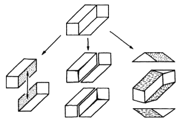
Figure 2. Three interpretations of Thiéry's figure.
2.2 Likely and unlikely figures
Two common examples of likely figures, the impossible truncated pyramid and Huffman's corner (Huffman 1971; Kulpa 1983), are shown in figures 3a and 3b.
Here our brain makes a double mistake: first, it chooses impossible interpretations of these figures (a truncated pyramid with a triangular base, and a cut-out inside corner of a thick-walled box); second, it considers these impossible interpretations to be quite feasible. The impossibility of these interpretations can be simply demonstrated (figures 3c and 3d). In the case of the pyramid (figure 3c), the three edges A, B, and C, being the lines of mutual intersection of three different planes, should intersect at a single point, but they do not (the same reasoning can also be applied to the impossible triangle in figure 1a). In the case of Huffman's corner (figure 3d) the drawing shows the planes A and B as intersecting along two different lines, whereas any two planes can only intersect along a single straight line.
A symmetrically opposite situation is responsible for the so-called unlikely figures. Our brain usually arrives at possible interpretations of these figures, but treats them doubtfully, considering them suspect or impossible (Huffman 1971; Gillam 1979). The figures in figure 4 are simple examples-their usual interpretations as, respectively, a skewed plane-faced die, a plank with a slantwise-cut cavity at the edge (Huffman 1971), and a spatially skewed pentagon made of straight bars (the Césari pentabar, see Térouanne 1983) are quite possible, although do not appear so to many observers.

Figure 3. Two examples of likely figures: (a) the impossible truncated pyramid, and (b)
Huffman's corner, together with proof of their impossibility [(c) and (d) respectively].

Figure 4. Three examples of unlikely figures.
2.3 General classification of figures
The most general classification of impossible and other related figures is summarized in table 1 (Kulpa 1983). However, because of the inherently psychological nature of these phenomena, this classification is not absolute-different people on different occasions might classify the same drawings differently. Also, within any single class, different figures might show different degrees of membership in the class. For example, it can be observed that some impossible figures look less impossible than others.
Table 1. The general classification of figures.
| Interpretation judged as | Interpretation chosen | |
| Possible | Impossible | |
| Possible | possible figures | likely figures |
| Impossible | unlikely figures | impossible figures |
2.4 Degrees of impossibility
Certain impossible figures seem to be 'very much impossible' and strongly contradictory, so that their possible interpretations are very hard to find (see figure 1b, the devil's fork). Other figures look a little less impossible, and their possible interpretations, although not easy to find, do not seem to be so completely inconceivable (see figure 1a, the impossible triangle or tribar). Other figures look puzzling, but their possible interpretations are rather easy to find, for example Thiéry's figure (figures 1c and 2). There are also figures that look 'nearly impossible', but whose possible interpretations are, however, so easy to find that they usually come as second thoughts of the observer who is initially slightly disturbed by their unusual structure. For example, for the nearly impossible beam (figure 5a), the impossible interpretation that first comes to mind is close to that of Thiéry's figure – two parallelepipeds seen from different viewpoints and improperly joined (figure 5b) – but other possible interpretations soon also appear (Kulpa 1983; Reutersvärd and Kulpa 1984), namely a half-ring with a square cross-section (figure 5c), or a slantwise-cut beam with a square cross-section (figure 5d).
Unfortunately, owing to the essentially psychological nature of the impossibility judgement, an objective formally definable quantitative measure of impossibility seems, at the moment, to be inaccessible despite numerous attempts in this direction (Huffman 1971; Cowan 1977; Cowan and Pringle 1978; Sugihara 1982a; Térouanne 1980, 1983).
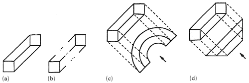
Figure 5. (a) A nearly impossible beam, (b) the impossible interpretation that first comes
to mind, and (c), (d) two possible interpretations of it.
3 Sources of impossibility
A drawing seems impossible when the local interpretations of its parts are mutually inconsistent. Therefore, the significant features of spatial interpretations that are determined more or less locally and can contradict analogous features of other adjoining fragments provide us with probable sources of impossibility. Through the analysis of various impossible (and possible) figures I was able to distinguish three general types: object-background contradiction, position-estimation contradiction, and surface-form contradiction (Kulpa 1983).
3.1 Object - background contradiction
As an impossibility source, this is the most powerful, because it violates the most basic distinction – that between a part of the background and an element of the object. For the casual observer this is usually the most noticeable and eye-catching feature, and the most difficult to interpret as possible. Figure 6a shows an almost 'pure' case of the occurrence of object - background contradiction, and figure 6b a recently discovered variant of this contradiction (Kulpa 1983; Reutersvärd and Kulpa 1984; Ernst 1985, 1986) – with a shadow cast at the object and at its background.
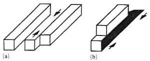
Figure 6. Two examples of figures with object - background contradiction, (a)
a nearly 'pure' example, (b) a recently discovered variant.
3.2 Position-estimation contradiction
Position-estimation contradiction is a very common source of impossibility and is found in many impossible figures in various variants and forms. It occurs when the relative position of the same object fragment is estimated differently according to differing partial contexts of the fragment. For example, in the impossible staircase (Penrose and Penrose 1958; Kulpa 1983), and in Huffman's block (Huffman 1971; Kulpa 1983), the contradiction concerns the vertical position of a fragment (see figure 7).
Step A of the staircase (figure 7a) is, evidently, below step B. Equally evidently it is above step C, but, through the sequence of steps along the right-hand corner of the staircase, step C is above step B. and therefore step A, being above step C, should also be above step B. In the block (figure 7b), edge A is evidently below edge B, separated from it by a vertical edge. But both A and B belong to the same upper horizontal face of the block, and thus A should be at the same level as B.
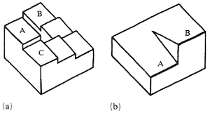
Figure 7. Two examples of vertical position-estimation contradiction:
(a) the impossible staircase; (b) Huffman's block.
3.2.1 Depth-estimation contradiction.
Very often we encounter a variant of the position-estimation contradiction in which the estimates of position in depth, that is, in the direction perpendicular to the plane of the drawing, differ for the same fragment of the figure. For example, in the tribar (figure 8), corners L and R suggest that the left beam goes away from us and the right one comes toward us, so that end L' should be farther out than R'. But in the full triangle, ends L' and R' are joined, and thus they are at the same depth.
Generally, the position-estimation impossibility source is less conspicuous than the figure - background one: it can sometimes be found in likely figures. It is also easier to resolve into a possible interpretation, although often of quite tricky a structure (Gregory 1970; Kulpa 1983; Ernst 1985, 1986).
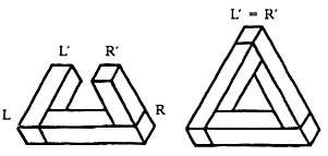
Figure 8. Depth-estimation contradiction in the tribar.
3.3 Surface-form contradiction
This very common phenomenon often arises as a by-product of other sources. It occurs when the estimated spatial conformation of an area in the drawing (representing a fragment of the object's surface) differs according to differing partial contexts of the area. Usually, this contradiction can easily be overcome by visualizing a smooth transition (that is, without edges and wrinkles) of the surface from the one estimated form to the other.
There are two common special cases of this impossibility source – the twisted-plane contradiction and the planar-curved contradiction.
3.3.1 Twisted-plane contradiction.
Here a planar face of the object admits two contradictory estimations of its spatial orientation (for example, horizontal versus vertical). In almost pure form it occurs in Ernst's dibar (Ernst 1985; figure 9a).
3.3.2 Planar-curved contradiction.
Here the contradiction occurs between two basic forms of the face of the object – a plane (planar surface) and non-piane (curved surface). It can be illustrated by the simple double-rod figure (figure 9b).
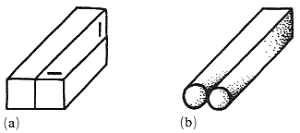
Figure 9. Two examples of surface-form contradiction:
(a) twisted-plane contradiction in Ernst's dibar, (b) planar-curved
contradiction in the double-rod figure.
3.4 Mixed cases
In most impossible figures one can usually find several different impossibility sources, one sometimes being a consequence of another. A good example is the devil's fork (figure 1b), where in three places the object - background distinction is violated, in three places a flat stripe changes into a cylindrical one, still another stripe parallel to the plane of the drawing twists to a skewed position, and the prongs, as well as one of the stripes, admit different depth estimations. Is it surprising that the fork looks so "very much impossible"?
Huffman's block (figure 7b) might, with some effort, be interpreted also in terms of the planar-curved contradiction. Its upper surface, bounded by pair-wise parallel straight edges, seems to be a horizontal plane. But the position of edges A and B proves the surface cannot be planar, hence the contradiction.
Note also that the 'pure' example of the object - background contradiction (figure 6a) is not so pure – the fragment marked by arrows, besides turning from object to background, also changes its vertical position accordingly. Figure 6b shows another simple example of the interdependence of different sources – the object - background contradiction, obtained by the self-shadow changing into the cast-shadow, also produces the vertical - horizontal contradiction in the shaded area.
4 Multibars
This is a class of figures introduced (under the name of cornered toruses) by Cowan (1977) and also investigated by others (Draper 1978; Térouanne 1980, 1983; Kulpa 1981). Often also called 'impossible polygons', these figures are built of a number of square beams (or bars) joined at their ends to form n-sided polygons (figure 10).
Beam joints, or corners, of the polygons, can be seen from four basically different directions. As a result, they appear in the drawing in one of the four configurations, denoted by the symbolic codes N, M, Z, and S, respectively (figure 11), through which we can define a symbolic encoding of multibars.

Figure 10. Four examples of multibars.

Figure 11. Four basic corner configurations.
4.1 Symbolic encoding of multibars
The sequence of codes of all corners of a multibar (by convention listed in clockwise order) constitutes a starting point for such an encoding. The examples of figure 10 are described by the sequences SSS, NSNS, NZZM, and NMSNMS, respectively.
Because rotation of the figure in the plane of the drawing does not change its structure, the encoding sequence is cyclically invariant, that is, all its cyclical shifts in fact represent the same figure (the choice of the first corner is not significant). For example, the encodings NZZM, ZZMN, ZMNZ, and MNZZ all represent the same figure (figure 10c). However, if we introduce an ordering into the corner codes [the sequence N < M < ;Z < S is usual here [Cowan 1977; Kulpa 1981)] and subsequently, from all its cyclical shifts, we choose the (lexicographically) first encoding of a figure as its 'canonical' description, we will arrive at a one-to-one correspondence between figures and their code sequences.
For further ordering of multibars we might use various kinds of geometrical [or topological (Cowan 1977)] relations. The most basic are given by certain geometrical transformations.
4.2 Geometrical transformations of multibars
These are the operations of inversion (or mirror reflection) and obversion (or 'look from behind'), denoted by I and O respectively. The operation of the so-called eversion is obtained as a superposition of the previous two, and it is denoted by E, that is, E = IO = OI. These operations, although geometrically defined, are also easily expressed in terms of symbolic code transformations. Namely, I changes Z into S, and vice versa, O changes M into N, and vice versa, and both reverse the sequence of corner codes (figure 12). All these operations, together with the identity transformation, constitute a commutative group of transformations.
Again, within every group of figures closed with respect to operations I, O, and E, the figure with the lexicographically first code is chosen as the canonical form (denoted symbolically by T) and all the groups are then listed in the (lexicographical) sequence of their canonical descriptions. Thus a neat classification scheme reflecting a basic mathematical structure of the sets of n-bars is finally obtained.
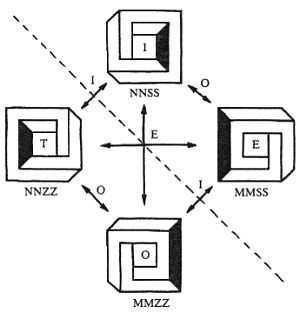
Figure 12. Geometrical transformations of a tetrabar.
4.3 Computer generation of multibars
The combinatorial algorithm generating all canonical sequences of corner codes in the lexicographical order is in fact a generator of all the multibar figures (possible and impossible) and it can be easily programmed for a computer. Combined with the classification scheme given by the group of geometrical transformations (TIOE), it has been implemented by the author (Kulpa 1981). The program has produced various tables of multibars, including the listing of all tribars given in table 2.
Table 2. Computer listing of all tribars (total number of tribars = 24).
| Number | T | I | O | E |
| 1 | NNN | =T | MMM | =O |
| 2 | NNM | =T | NMM | =O |
| 3 | NNZ | NNS | MMZ | MMS |
| 4 | NMZ | NSM | =T | =I |
| 5 | NMS | NZM | =T | =I |
| 6 | NZZ | NSS | MZZ | MSS |
| 7 | NZS | =T | MSZ | =O |
| 8 | NSZ | =T | MZS | =O |
| 9 | ZZZ | SSS | =T | =I |
| 10 | ZZS | ZSS | =T | =I |
We can easily observe the position of our impossible triangle (SSS) – its code is 9I, and it is a mirror reflection of the tribar ZZZ, encoded as 9T (see figure 13a). The obversion (backside view) of the tribar ZZZ is the same as the tribar itself (that is, also ZZZ); whereas the eversion is identical to the mirror reflection (that is, SSS). The example tetrabars NSNS and NZZM (figures 10b and 10c) are listed in a table of tetrabars under entries 15I and 14I, respectively, and the hexabar NMSNMS (figure 10d) is listed as 139T.
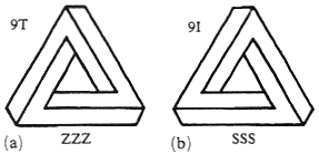
Figure 13. Two tribars number 9, together with their codes: (a) 9T, (b) 9I.
4.4 Concave and rounded multibars
In my discussions of multibars I have so far taken for granted the tacit assumption that they form only convex polygons. By relaxing this assumption one additionally obtains a multitude of concave multibars, containing concave corners (see figure 14).
It is easy to include the concave multibars within the encoding scheme. We only have to mark the codes of concave comers in some way, for example by an apostrophe. The figures in figure 14 then obtain the respective codes NZSS'Z, MNZZ'SN, and NZN'ZM'ZM.
By adding new forms of corners, we can create, for example, rounded multibars, containing rounded corners of two possible forms denoted by the symbols Z0 and S0 (figure 15). Thus, our multibar family again increases to include such figures as those in figure 16, encoded symbolically as Z0Z0, NS0S, and ZZMS'0MS respectively.
The multibar family can be still further extended by the addition of self-intersecting polygons. Some examples can be found in Draper (1978), Térouanne (1980), and elsewhere. In this case the problems of cataloguing possible types of intersections and encoding the figures become more complicated and will not be pursued here.
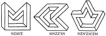
Figure 14. Three examples of concave multibars, with their codes.

Figure 15. Two types of rounded corners
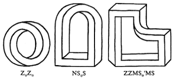
Figure 16. Three examples of multibars with rounded corners, with their codes.
4.5 Counting multibars
The combinatorial nature of my method for enumerating the class of multibars makes the derivation of formulas counting the number of different multibars comparatively easy (Kulpa 1981). Let us denote by Mc(n) the number of multibars with n corners of c types (n = 1, 2, ...; c = 4 for normal convex multibars, c = 8 for the multibar class that also admits concave corners, and c = 12 when rounded corners – convex and concave – are added).
There are c ↑ n different sequences of n elements of c types. The number of corresponding multibars is smaller because all cyclical shifts of a given sequence, although usually different, represent the same single multibar. Moreover, if for every sequence, all n cyclical shifts of the sequence were different, that is, if every multibar had exactly n different cyclically equivalent representations, then we would have
![]()
However, some groups of cyclically equivalent sequences contain fewer than n elements (for example, the sequence NNN is cyclically equivalent only to itself, and the four-element sequence ZSZS is cyclically equivalent to only one different sequence, SZSZ). Summing up, we get the following lower and upper estimates for Mc(n):
|
|
(1) |
where ![]() x
x![]() denotes the smallest integer not less than x.
denotes the smallest integer not less than x.
When n is a prime number, all sequences with fewer than n cyclically equivalent sequences are homogenous, that is, are of the form pp...p, where p is one of c types of elements. For all c homogenous sequences, their groups of cyclical equivalence contain only one sequence, that is, n – 1 fewer than the groups of all other nonhomogenous sequences. Thus, n × Mc(n) is greater than c ↑ n by exactly c(n – 1), and, in this case, Mc(n) can be exactly calculated (for n a prime number):
|
|
(2) |
Unfortunately, when n is not a prime number, the situation becomes more complicated, and the exact formula is harder to derive. Luckily, the lower estimate for Mc(n) happens to be fairly accurate – when n is a prime number it differs from Mc(n) by less than c [see equation (2)]; for other values of n the difference is greater, but still small (it depends on the number of divisors of n). Table 3 gives exact numbers of multibars for c = 4, as well as lower estimates for c=4, 8, and 12.
Table 3. Number of multibars, Mc(n), with n corners of c types, c = 4 for normal convex multibars, c = 8 for the multibar class that also admits concave corners, and c = 12 when rounded corners (convex and concave) are added.
| n | Exact value c = 4 |
Lower estimate |
||
| c = 4 | c = 8 | c = 12 | ||
| 1 | 4 | 4 | 8 | 12 |
| 2 | 10 | 8 | 32 | 72 |
| 3 | 24 | 22 | 171 | 576 |
| 4 | 70 | 64 | 1024 | 5184 |
| 5 | 208 | 205 | 6554 | 49767 |
| 6 | 700 | 683 | 43691 | 248832 |
| 7 | 2344 | 2341 | 299594 | 5118830 |
5 Striped figures
Various kinds of impossible figures (Robinson and Wilson 1973; see figure 17a) can be interpreted as a sequence of stripes, that is, elongated areas separated by straight parallel edges, according to the general scheme of figure 17b, where the symbols I1, I2, ..., In and J1, J2, .... Jn denote appropriate (spatial) interpretations of the stripes as suggested by pictorial contexts at their respective endings. When interpretations I and J of a stripe are different a contradiction occurs, and perhaps eventually produces an impossible figure.
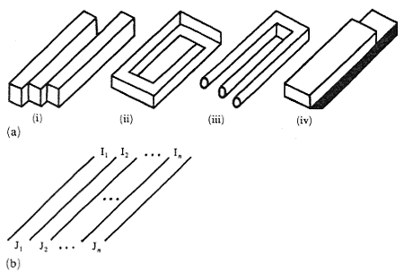
Figure 17. (a) Four examples of striped figures, (b) general scheme of a striped figure.
5.1 Symbolic encoding of striped figures
We can distinguish many different interpretations (or classes of interpretations) of the stripes that might occur in drawings. If we denote them by appropriate symbols, for example:
O - object,
B - background,
P - planar,
C - curved,
Vr - vertical plane seen from right,
Vl - vertical plane seen from left,
Ha - horizontal plane seen from above,
Hb - horizontal plane seen from below,
S - shadow,
and so on, then we can create a whole system for the symbolic encoding of a wide class of figures as well as a method for their classification and, eventually, systematic generation.
The codes, with the general form
![]()
for the four example figures given in figure 17a can be given as follows:
| (i) | |||
| (ii) |  |
||
| (iii) |  |
or |  |
| (iv) |  |
Many impossible figures (or their significant parts) that show the object-background or surface-form contradictions can be interpreted as striped figures. However, figures with the position-estimation contradiction (for example, the tribar and the impossible staircase) usually cannot be interpreted and described in this way.
6 Conclusions
I have briefly introduced several ordering schemes for the classification and structural description of impossible figures. For all flat figures that possess spatial interpretations these schemes include:
- the general division into classes of possible, impossible, likely, and unlikely figures;
- identification of the fundamental impossibility sources; and
- a structural description of two broad classes of impossible figures-multibars and striped figures.
Such an ordering will facilitate reference, unify terminology, and establish the conceptual framework for further investigations of the subject. It should also facilitate the choice and systematic generation of various types of figures (for example, in systematic psychological experiments).
The paper is only an introduction to the subject, and considerable research in this area is still under way. Several other classification principles, not described here, have also been proposed (Guiraud and Lison 1976, Sugihara 1982a, 1982b), but many impossible figures still remain unexplored and unclassified (Ernst 1976, 1985, 1986; Draper 1978; Yturralde 1978; Reutersvärd and Kulpa 1984).
Acknowledgements. The preparation of this paper was partially supported by Research Project No 0.69 of the Polish Academy of Sciences.
References
- Cowan T M, 1977 "Organizing the properties of impossible figures" Perception 6 41-56
- Cowan T M, Pringle R, 1978 "An investigation of the cues responsible for figure impossibility" Journal of Experimental Psychology. Human Perception and Performance 4 112-120
- Cresswell M J, 1983 "A Highly impossible scene" in Meaning, Use and Interpretation of Language eds R. Bäuerle, C. Schwarze, A. von Stechow (Berlin: De Gruyter) pp. 62-77
- Draper S W, 1978 "The Penrose Triangle and a Family of Related Figures" Perception 7 283-296
- Ernst B, 1976 The Magic Mirror of M.C. Escher (New York: Ballantine Books)
- Ernst B, 1985 Avonturen met Onmogelijke Figuren (Amsterdam: Aramith Uitgevers)
- Ernst B, 1986 Het Begoochelde Oog Onmogelijke en Meerzinnige Figuren (Amsterdam: Meulenhoff/Landshoff)
- Gillam B, 1979 "Even a possible figure can look impossible!" Perception 8 229-232
- Gregory R L, 1970 The Intelligent Eye (London: Weidenfeld and Nicolson)
- Guiraud J, Lipson P, 1976 Systematique des Figures Reversibles (Bruxelles: Gestetner)
- Huffman D A, 1971 "Impossible objects as nonsense sentences" in Machine Intelligence 6 eds B Heltzer, D Michie (Edinburgh: Edinburgh Unversity Press) pp. 295-323
- Kulpa Z, 1981 "Generacja i klasyfikacja figur niemożliwych z klasy tzw. 'rogatych torusów'" ("Generation and classification of impossible figures of the so-called 'cornered toruses' class") internal report (in Polish) Institute of Biocybernetics and Biomedical Engineering, Warsaw, 28 pages plus computer listings
- Kulpa Z, 1983 "Are impossible figures possible?" Signal Processing 5 201-220
- Penrose L S, Penrose R, 1958 "Impossible objects a special type of visual illusion" British Journal of Psychology 49 31-33
- Reutersvärd O, Kulpa Z, 1984 Challenge to Geometry – Impossible Figures exhibition catalogue (Łódź, Poland Art Museum of Łódź)
- Robinson J O, Wilson J A, 1973 "The impossible colonnade and other variations of a well known-figure" British Journal of Psychology 64 363-365
- Sugihara K, 1982a "Classification of impossible objects" Perception 11 65-74
- Sugihara K, 1982b "Mathematical structures of line drawings of polyhedrons - toward man-machine communication by means of line drawings" IEEE Transactions of Pattern Analysis and Machine Intelligence 4 458-469
- Térouanne E, 1980 "On a class of 'impossible' figures: a new language for a new analysis" Journal of Mathematical Psychology 22 24-46
- Térouanne E, 1980 "'Impossible' figures and interpretations of polyhedral figures" Journal of Mathematical Psychology 24 370-405
- Thiéry A, 1895 "Über geometrisch-optische Täuschungen" Philosophische Studien 11 307-370
- Thro E B, 1983 "Distingushing two classes of impossible objects" Perception 12 733-751
- Young A W, Deręgowski J B, 1981 "Learning to see impossible" Perception 10 91-105
- Yturralde J M, 1978 "Ambigous structures" in Hypergraphics - Visualizing Complex Relationships in Art, Science and Technology ed D W Brisson (Boulder: CO Westview Press) pp. 177-185
